AC Power:
ALTERNATING CURRENT AND VOLTAGE
Many of the important technical characteristics of power systems have to do with their use of alternating current (a.c.) instead of direct current (d.c.). In a d.c. circuit, the polarity always remains the same: the potential always stays positive on one side and negative on the other, and the current always flows in the same direction. In an a.c. circuit, this polarity reverses and oscillates very rapidly. For power systems in the United States, the a.c. frequency is 60 hertz (Hz) or 60 cycles per second, meaning that the direction of voltage and current are reversed, and reversed back again 60 times every second.
Historical Notes
The main reason for using a.c. in power systems is that it allows raising and lowering the voltage by means of transformers. As we will see in Section 6.2, transformers cannot be operated with d.c. It is still possible to change the voltage in a d.c. circuit, but it requires far more sophisticated and expensive equipment that had not been invented in the early days of electric power. The first power systems, which operated on d.c., were therefore limited to rather low transmission voltages: although the generators could have been designed to produce power at a higher voltage, safety considerations at the customer end dictated that the voltage is kept low. Consequently, line losses were a major problem and in effect limited the geographic expansion of power systems. After the transformer was introduced in the 1880s, d.c. and a.c. systems spent some years in fierce competition (the “Battle of the Currents”), with Edison and Westinghouse as prominent advocates on either side. The major obstacles in the way of the alternating current approach—namely, concerns about the safety of high-voltage transmission, as well as the challenge of designing an a.c. motor—were largely resolved by the mid-1890s.1
The choice of frequency for a.c. the power represented a compromise between the needs of different types of equipment. During the early years of a.c. systems, numerous different frequencies ranging from 25 to 133 1 3 cycles were used.2 For generators, lower frequencies tend to be preferable because this requires fewer magnetic poles inside the rotor (see Section 4.1), though this constraint became less significant as high-speed steam turbines supplemented and replaced slow-moving hydro turbines and reciprocating steam engines. For transmission, lower frequencies are especially desirable because a line’s reactance increases with frequency and constrains the amount of power that can be transmitted on a given line (see Sections 3.2 and 6.5). For loads, on the other hand, higher frequencies are often preferable. This is particularly true for incandescent lamps, whose flickering becomes more and more noticeable to the human eye at lower frequencies. After due consideration of the different types of equipment already in use and the prospects for adopting new designs, efforts to standardize power frequency finally resulted in convergence to a 60 cycle standard in the United States and 50 cycles in Europe.
Mathematical Description
A sine wave represents the cyclical increase and decrease of a quantity over time. The oscillation of voltage and current in an a.c. the system is modeled by a sinusoidal curve, meaning that it is mathematically described by the trigonometric functions of sine or cosine. In these functions, time appears not in the accustomed units of seconds or minutes, but in terms of an angle.
A sinusoidal function is specified by three parameters: amplitude, frequency, and phase. The amplitude gives the maximum value or height of the curve, as measured from the neutral position. (The total distance from crest to trough is thus twice the amplitude.) The frequency gives the number of complete oscillations per unit time. Alternatively, one can specify the rate of oscillation in terms of the inverse of frequency, the period. The period is simply the duration of one complete cycle. The phase indicates the starting point of the sinusoid. In other words, the phase angle specifies an angle by which the curve is ahead or behind of where it would be, had it started at time zero. Graphically, we see the phrase simply as a shift of the entire curve to the left or right. The phase angle is usually denoted by f, the Greek lowercase phi.
Expressing time as an angle allows us to take a sine or cosine of that number. For example, the sine of 30 degrees is 1 2, but there is no such thing as the sine of 30 seconds. The argument of a sinusoidal function (the variable or object of which we find the sine) must be dimensionless, that is, without physical dimension like time, distance, mass, or charge. An angle, though measured in units of degrees or radians, has no physical dimension; it really represents a ratio or fraction of a whole.
This is consistent with the fact that a sine function represents a relationship between two quantities: in a right triangle, the sine of one angle is the ratio of lengths of two of the sides (the reader may recall “opposite over hypotenuse” for sine, and “adjacent over hypotenuse” for cosine). Time as an angle means time as a certain fraction of a whole. Turning time into an angle or fraction is logical only because in an oscillation, time is cyclical; the process repeats itself. We do not care whether we are on our first or four-hundredth swing, but rather about where in the oscillation we find ourselves at a given instant. One complete oscillation, the duration or period of which would be 1/60th of a second for 60 Hz, is taken to correspond to a full circle of 360 degrees. Any angle can be understood, then, as specifying a fraction or multiple of that complete oscillation.
Plotted against angle on the horizontal axis, the height of the sine curve is simply the value of the sine for each angle, scaled up by a factor corresponding to the amplitude. As the angle is increased, it eventually describes a complete circle, and the function repeats itself. In the context of sinusoidal functions, angles are often specified in units of radians (rad) rather than degrees. Radians refer to the arc described by an angle. The conversion is simple. Since the circumference of an entire circle is given by 2pr, where is the radius and p (pi)¼3.1415, 2p radians correspond to 3608. (The radius is left out since the size of the circle is arbitrary; in this way, we are only referring- ring to the angle itself.) Any fraction of a radian, then, represents a fraction of a circle, or a number of degrees: p rad¼1808 or one-half cycle; p/2 rad¼908 or one-quarter cycle, and so on. Figure 3.1 illustrates a sine wave with both units of angle.
The frequency of a sinusoidal function is often given in terms of radians per second, in which case it is called an angular frequency. Angular frequencies are usually denoted by v, the Greek lowercase omega, as opposed to for n (Greek lowercase nu) for frequency.
The quantity Imax is the maximum value or amplitude of the current. Since the value of a sine or cosine varies betweenþ1 and 21, the actual current oscillates between þImax and 2Imax. The time t is measured in seconds, and, when multiplied by the angular frequency v, gives a number of radians. In the simplest case, shown in the upper portion of Figure 3.2, there is no phase shift, meaning that f is zero and the curve starts at zero. To illustrate the more general case shows the curve shifted over to the left by an angle f. Note that the phase shift affects neither frequency nor amplitude of the curve; it simply amounts to a difference in what time is considered “zero” in comparison to some other curve, which will become important later when we consider the relative timing of current and voltage. The same discussion as for current holds for the voltage, which is written
V(t) ¼ Vmaxsin(vtþfV)
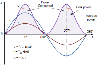
The subscripts on the phase angles are there to indicate that current and voltage do not necessarily have the same phase; that is, their maximum values do not necessarily coincide in time (Section 3.3 addresses the phase shift between current and voltage). In practice, current and voltage waveforms do not conform to this precise mathematical ideal; in some cases, interpreting them as sinusoidal requires a vivid imagination. While they will always be periodic (i.e., repeating themselves), they may not be round and smooth like the proper sinusoidal curve. The discrepancy results in part from the internal geometry of the generators and in part from harmonic distortion caused by loads and other utility equipment. The degree of conformance to the shape of a sine curve, or “good waveform,” is one aspect of power quality. The poor waveform may not be a problem, though, unless there are sensitive loads.
The rms Value
For most applications, we are only interested in the overall magnitude of these functions. Conceivably, we could just indicate the amplitude of the sine wave, but this would not represent the quantity very well: most of the time, the actual value of the function is much less than the maximum. Alternatively, we could take a simple arithmetic average or mean.
However, since a sine wave is a positive half the time and negative the other half, we would just get zero, regardless of the amplitude; this average would contain no useful information. What we would like is some way of averaging the curve that offers a good representation of how much current or voltage is actually being supplied: a meaningful physical measure; something of an equivalent to a d.c. value. Specifically, we would like average values of current and voltage that yield the correct amount of power when multiplied (see Section 3.4). Fortunately, such an average is readily computed: it is called the root mean square (RMS) value.
The RMS value is derived by first squaring the entire function, then taking the average (mean), and finally taking the square root of this mean. Squaring the curve eliminates the negative values since the square of a negative number becomes positive. illustrates this process with the curves labeled V(t) and V2(t)—though we could just as well have chosen the current I(t)—where the squared sinusoid while retaining the same basic shape, is now compressed in half. If we arbitrarily label the vertical axis in units such that the amplitude
ALTERNATING CURRENT AND VOLTAGE
Vmax ¼1, it is obvious that the square wave has the same amplitude (12 ¼1). Because the squared curve resides entirely in the positive region, it is now possible to take a meaningful average. Indeed, because the curve is still perfectly symmetric, its average is simply one half the amplitude. The only counterintuitive step now consists of renormalizing this average value to the original curve before squaring, which is accomplished by taking the square root: basically, we are just going back and undoing the step that made the curve manageable for averaging purposes. Since 1 2 is less than 1, its square root is greater than itself; it comes toffiffi 1 2 p ¼ 1= ffiffiffi 2p ¼ 0:707. Thus, the RMS value of a sine curve is 0.707 of the original amplitude.
Utility voltages and currents are almost always given as RMS values.
For example, 120 V is the RMS voltage for a residential outlet. Note that when the arms voltage and current are multiplied together, the product gives the correct amount of power transmitted (see Section 3.3).
Example
If 120 V is the RMS value of the household voltage, what is the amplitude?
Since
Vrms ¼ 1= ffiffiffi 2p Vmax, Vmax ¼ ffiffiffi 2p 120V ¼ 169:7V.
The maximum instantaneous value of the voltage is also of interest because it determines the requirements for electrical insulation on the wires and other energized parts. In fact, one argument against a.c. in the early days was that it would be less economical due to its insulation requirements, which are greater by a factor of ffiffiffi 2p than those for d.c. equipment transmitting the same amount of power. For current, the instantaneous maximum is relatively uninteresting because current limitations are related to resistive heating, which happens cumulatively over time.

ALTERNATING CURRENT AND VOLTAGE
Many of the important technical characteristics of power systems have to do with their use of alternating current (a.c.) instead of direct current (d.c.). In a d.c. circuit, the polarity always remains the same: the potential always stays positive on one side and negative on the other, and the current always flows in the same direction. In an a.c. circuit, this polarity reverses and oscillates very rapidly. For power systems in the United States, the a.c. frequency is 60 hertz (Hz) or 60 cycles per second, meaning that the direction of voltage and current are reversed, and reversed back again 60 times every second.
Historical Notes
The main reason for using a.c. in power systems is that it allows raising and lowering the voltage by means of transformers. As we will see in Section 6.2, transformers cannot be operated with d.c. It is still possible to change the voltage in a d.c. circuit, but it requires far more sophisticated and expensive equipment that had not been invented in the early days of electric power. The first power systems, which operated on d.c., were therefore limited to rather low transmission voltages: although the generators could have been designed to produce power at a higher voltage, safety considerations at the customer end dictated that the voltage is kept low. Consequently, line losses were a major problem and in effect limited the geographic expansion of power systems. After the transformer was introduced in the 1880s, d.c. and a.c. systems spent some years in fierce competition (the “Battle of the Currents”), with Edison and Westinghouse as prominent advocates on either side. The major obstacles in the way of the alternating current approach—namely, concerns about the safety of high-voltage transmission, as well as the challenge of designing an a.c. motor—were largely resolved by the mid-1890s.1
The choice of frequency for a.c. the power represented a compromise between the needs of different types of equipment. During the early years of a.c. systems, numerous different frequencies ranging from 25 to 133 1 3 cycles were used.2 For generators, lower frequencies tend to be preferable because this requires fewer magnetic poles inside the rotor (see Section 4.1), though this constraint became less significant as high-speed steam turbines supplemented and replaced slow-moving hydro turbines and reciprocating steam engines. For transmission, lower frequencies are especially desirable because a line’s reactance increases with frequency and constrains the amount of power that can be transmitted on a given line (see Sections 3.2 and 6.5). For loads, on the other hand, higher frequencies are often preferable. This is particularly true for incandescent lamps, whose flickering becomes more and more noticeable to the human eye at lower frequencies. After due consideration of the different types of equipment already in use and the prospects for adopting new designs, efforts to standardize power frequency finally resulted in convergence to a 60 cycle standard in the United States and 50 cycles in Europe.
Mathematical Description
A sine wave represents the cyclical increase and decrease of a quantity over time. The oscillation of voltage and current in an a.c. the system is modeled by a sinusoidal curve, meaning that it is mathematically described by the trigonometric functions of sine or cosine. In these functions, time appears not in the accustomed units of seconds or minutes, but in terms of an angle.
A sinusoidal function is specified by three parameters: amplitude, frequency, and phase. The amplitude gives the maximum value or height of the curve, as measured from the neutral position. (The total distance from crest to trough is thus twice the amplitude.) The frequency gives the number of complete oscillations per unit time. Alternatively, one can specify the rate of oscillation in terms of the inverse of frequency, the period. The period is simply the duration of one complete cycle. The phase indicates the starting point of the sinusoid. In other words, the phase angle specifies an angle by which the curve is ahead or behind of where it would be, had it started at time zero. Graphically, we see the phrase simply as a shift of the entire curve to the left or right. The phase angle is usually denoted by f, the Greek lowercase phi.
Expressing time as an angle allows us to take a sine or cosine of that number. For example, the sine of 30 degrees is 1 2, but there is no such thing as the sine of 30 seconds. The argument of a sinusoidal function (the variable or object of which we find the sine) must be dimensionless, that is, without physical dimension like time, distance, mass, or charge. An angle, though measured in units of degrees or radians, has no physical dimension; it really represents a ratio or fraction of a whole.
This is consistent with the fact that a sine function represents a relationship between two quantities: in a right triangle, the sine of one angle is the ratio of lengths of two of the sides (the reader may recall “opposite over hypotenuse” for sine, and “adjacent over hypotenuse” for cosine). Time as an angle means time as a certain fraction of a whole. Turning time into an angle or fraction is logical only because in an oscillation, time is cyclical; the process repeats itself. We do not care whether we are on our first or four-hundredth swing, but rather about where in the oscillation we find ourselves at a given instant. One complete oscillation, the duration or period of which would be 1/60th of a second for 60 Hz, is taken to correspond to a full circle of 360 degrees. Any angle can be understood, then, as specifying a fraction or multiple of that complete oscillation.
Plotted against angle on the horizontal axis, the height of the sine curve is simply the value of the sine for each angle, scaled up by a factor corresponding to the amplitude. As the angle is increased, it eventually describes a complete circle, and the function repeats itself. In the context of sinusoidal functions, angles are often specified in units of radians (rad) rather than degrees. Radians refer to the arc described by an angle. The conversion is simple. Since the circumference of an entire circle is given by 2pr, where is the radius and p (pi)¼3.1415, 2p radians correspond to 3608. (The radius is left out since the size of the circle is arbitrary; in this way, we are only referring- ring to the angle itself.) Any fraction of a radian, then, represents a fraction of a circle, or a number of degrees: p rad¼1808 or one-half cycle; p/2 rad¼908 or one-quarter cycle, and so on. Figure 3.1 illustrates a sine wave with both units of angle.
The frequency of a sinusoidal function is often given in terms of radians per second, in which case it is called an angular frequency. Angular frequencies are usually denoted by v, the Greek lowercase omega, as opposed to for n (Greek lowercase nu) for frequency.
The quantity Imax is the maximum value or amplitude of the current. Since the value of a sine or cosine varies betweenþ1 and 21, the actual current oscillates between þImax and 2Imax. The time t is measured in seconds, and, when multiplied by the angular frequency v, gives a number of radians. In the simplest case, shown in the upper portion of Figure 3.2, there is no phase shift, meaning that f is zero and the curve starts at zero. To illustrate the more general case shows the curve shifted over to the left by an angle f. Note that the phase shift affects neither frequency nor amplitude of the curve; it simply amounts to a difference in what time is considered “zero” in comparison to some other curve, which will become important later when we consider the relative timing of current and voltage. The same discussion as for current holds for the voltage, which is written
V(t) ¼ Vmaxsin(vtþfV)
The subscripts on the phase angles are there to indicate that current and voltage do not necessarily have the same phase; that is, their maximum values do not necessarily coincide in time (Section 3.3 addresses the phase shift between current and voltage). In practice, current and voltage waveforms do not conform to this precise mathematical ideal; in some cases, interpreting them as sinusoidal requires a vivid imagination. While they will always be periodic (i.e., repeating themselves), they may not be round and smooth like the proper sinusoidal curve. The discrepancy results in part from the internal geometry of the generators and in part from harmonic distortion caused by loads and other utility equipment. The degree of conformance to the shape of a sine curve, or “good waveform,” is one aspect of power quality. The poor waveform may not be a problem, though, unless there are sensitive loads.
The rms Value
For most applications, we are only interested in the overall magnitude of these functions. Conceivably, we could just indicate the amplitude of the sine wave, but this would not represent the quantity very well: most of the time, the actual value of the function is much less than the maximum. Alternatively, we could take a simple arithmetic average or mean.
However, since a sine wave is a positive half the time and negative the other half, we would just get zero, regardless of the amplitude; this average would contain no useful information. What we would like is some way of averaging the curve that offers a good representation of how much current or voltage is actually being supplied: a meaningful physical measure; something of an equivalent to a d.c. value. Specifically, we would like average values of current and voltage that yield the correct amount of power when multiplied (see Section 3.4). Fortunately, such an average is readily computed: it is called the root mean square (RMS) value.
The RMS value is derived by first squaring the entire function, then taking the average (mean), and finally taking the square root of this mean. Squaring the curve eliminates the negative values since the square of a negative number becomes positive. illustrates this process with the curves labeled V(t) and V2(t)—though we could just as well have chosen the current I(t)—where the squared sinusoid while retaining the same basic shape, is now compressed in half. If we arbitrarily label the vertical axis in units such that the amplitude
ALTERNATING CURRENT AND VOLTAGE
Vmax ¼1, it is obvious that the square wave has the same amplitude (12 ¼1). Because the squared curve resides entirely in the positive region, it is now possible to take a meaningful average. Indeed, because the curve is still perfectly symmetric, its average is simply one half the amplitude. The only counterintuitive step now consists of renormalizing this average value to the original curve before squaring, which is accomplished by taking the square root: basically, we are just going back and undoing the step that made the curve manageable for averaging purposes. Since 1 2 is less than 1, its square root is greater than itself; it comes toffiffi 1 2 p ¼ 1= ffiffiffi 2p ¼ 0:707. Thus, the RMS value of a sine curve is 0.707 of the original amplitude.
Utility voltages and currents are almost always given as RMS values.
For example, 120 V is the RMS voltage for a residential outlet. Note that when the arms voltage and current are multiplied together, the product gives the correct amount of power transmitted (see Section 3.3).
Example
If 120 V is the RMS value of the household voltage, what is the amplitude?
Since
Vrms ¼ 1= ffiffiffi 2p Vmax, Vmax ¼ ffiffiffi 2p 120V ¼ 169:7V.
The maximum instantaneous value of the voltage is also of interest because it determines the requirements for electrical insulation on the wires and other energized parts. In fact, one argument against a.c. in the early days was that it would be less economical due to its insulation requirements, which are greater by a factor of ffiffiffi 2p than those for d.c. equipment transmitting the same amount of power. For current, the instantaneous maximum is relatively uninteresting because current limitations are related to resistive heating, which happens cumulatively over time.
Basic Knowledge of AC Power Current
 Reviewed by Unknown
on
June 13, 2018
Rating:
Reviewed by Unknown
on
June 13, 2018
Rating:
Reviewed by Unknown
on
June 13, 2018
Rating:


Very Insightful and well written post
ReplyDelete